|
| Using Bathymetric Data with Terra Vista to Build Bathymetric Marine Databases |
| |
| Using Bathymetric Data with Terra Vista to Build Bathymetric Marine Databases |
| |
1. SRTM. Elevation data land above sea level, 90m resolution.
2. DNC. Digital Nautical Chart information for land below and above sea level.
3. Terra Vista generated supplemental sounding point data. |
| |
| This document assumes basic knowledge of Terra Vista. General steps will be given, not every
key stroke. The user should be familiar with Terra Vista and terrain modeling before starting. |
| |
| The following steps have been tried and verified using Terra Vista 6.2.1 by Presagis Field
Application Engineer Rick Brooks on 102711. Please contact him if you have any questions
regarding this tutorial.Rick.brooks@presagis.com |
| |
| Source data considerations: |
|
1. In order to get a good and clean coast line, you should ensure your coastline linear vectors,
your land areal and sea areal, geospecific land imagery, and your above sea level terrain source
correlate exactly at the coastline. Correlated data sources will avoid terrain cliffs and terrain
sticking up out of the water along the coastline. If your data is not correlated, you will see
these artifacts in the output database. There are some routines in Global Mapper that may be
able to correct some of this by clipping source terrain files using area polygonal vector data, but
it is very important to have correlated source data for this reason.
If the data is not correlated, attempt to orthorectify the imagery to the terrain source file.
Then, correct the coastline data to the source imagery and terrain files based on your accuracy
requirements. |
| |
| 2. Bathymetric data sources sometimes have way more data than needed to build an accurate
Bathymetry database. A lot of DNC source vectors also contain overlapping coverages for the
coastlines and water surface and land vectors. You must sort through your vector data source
files and understand the attribution and what files will actually be used in the Bathymetric
build. You cannot just import all the DNC vector data and hit build in Terra Vista due to the
complexity of the DNC vector coverages and the differences in attribution among the different
nautical vector sources. |
| |
| Terra Vista Information: |
|
| We will use two projects to build and create the final database. The first project will create an
exported DTED file of the sea floor surface using the bathymetric sounding points, Bathymetric
contour lines, and the coastline linear vectors. The second project will create the bathymetric
database from the exported DTED from project 1 merged in Global Mapper to your above sea
level terrain and the rest of your source vectors. |
| |
| PHASE 1/Project 1. Using Bathymetric Data To Build subsurface DTED. |
| |
1. Make sure the '\source\bathymetry' and '\source\elevation' directories are available.
2. Open Terra Vista and start a new project, this will start the Interviewer.
3. On the Import Source Data panel, add only Culture data. Make sure VPF (VMAP) is enabled.
Select the file \source\bathymetry\DNC13\A1356285\TILEREF\TILEREF.AFT. This file contains
the extent of the Bathymetry data to help configure the project. Do not import any other files
yet.
- watch Messages window for "Ending VPF Import......." close Current Operations panel
and not interviewer.
4. On the Interviewer, press Next and accept defaults until the Calculate Gaming Area panel.
Press the Auto Calculate button. You May have to press twice. Press Next.
5. On the Tile Size and LODs panel, set Number of LODs to 1. Press OK to end the Interviewer.
6. Open the Thumbnail View (View/Thumbnail).
7. On the Gaming Area tab uncheck the "Snap Translation to Existing Block Grid" box.
|
| 8. Press the Edit Block Size button and set the Block Size to 1 degree, press OK. |
| |
The Number of Blocks should be X=1 and Y=1.
The Extents should be +21.0 to +22.0 and -158.5 to -157.5. |
|
| Note: At this time, you should check the projection, extents, and origin to ensure you are in the
correct location and have the correct setup. |
| |
| 9. In the Source Data Library, expand Culture Data and disable the TILEREF vector file. You will
not use this. It was only used to set up the project gaming area. |
| |
10. Select File/Import and import \source\bathymetry\DNC13\A1356285\HYD\SOUNDP.PFT.- This file contains Sounding Points which are elevations under the sea. The vectors are
already attributed properly, to verify you can check them in the Vector Editor and see that they
have an attribute named 'code' with value BE020. Also, they have an attribute named 'HDP'
which is the elevation under water. The value of this attribute is positive but Terra Vista knows
it should be negative (below sea level).
|
11. Select File/Import and import \source\bathymetry\TVSOURCE\MY_SOUNDP.vec- This file contains Terra Vista vector editor made sounding points to demonstrate that
the user can supplement the DNC data with their own data to correct or enhance missing
sounding information in the DNC data. Original DNC13 sounding points did not have any
sounding points for the ports in this dataset, so it was enhanced only as an exercise. Nothing
needs to be done to this file because the sounding points were properly attributed using the
vector editor. Select some of the points using the vector editor to review the attribution
applied.
|
12. Select File/Import and import \source\bathymetry\DNC13\A1356285\ECR\COASTL.LFT.- This file contains the coast lines as linear features and can be used as a break-line to
make sure the coastlines are exactly 0.0m MSL; not above or below the water surface. The
vectors are ready for use; to check them you can use the Vector Editor. They should have code
= BA010, and the linear vectors are made of vertices with a Z value of 0.0.
|
13. Select File/Import and import \source\bathymetry\DNC13\A1356285\HYD\HYDLINE.LFT- This file contains bathymetric contour linear features and can be used to provide a more
accurate and smooth bathymetric sea surface. You may want to slightly generalize these
features since they are integrated and could have thousands of vertices. They should have
code = BE010 and will use attribute CRV to describe the slope elevation with a positive number.
Terra Vista will treat this as a negative number.
|
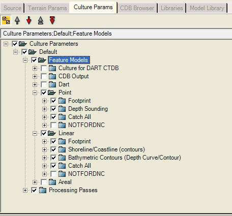
| 14. Go to Culture Parameters, expand Default, Feature Models. It is best to disable all feature
models which are not needed for bathymetric processing. To do this, create a new folder under
Point called NotForDNC. Put every Point Feature Model into this new Folder except Footprint,
Depth Sounding, and Catch All. Then disable the NotForDNC folder. |
| |
| 15. Do the same thing for linears. Create a new NotForDNC folder and put everything in the
new folder except Footprint, Shoreline/Coastline(contours), Bathymetric Contours (Depth
Curve/Contour), and Catch All. Then disable the NotForDNC folder. |
| |
| 16. Disable all other feature models to include the Dart, CDB, and Areal top-level folders. We do
not need them for this build. |
| |
| 17. At this point it is probably a great idea to go check the feature models under points and
linears that are enabled for this build. Check the following. |
| |
| Points: |
| Depth Sounding Feature model: Ensure the following run records are enabled and correct. |
| |
Point Layout: integrated is set on Output layout
Generate Point
Set Point Elevations: Height Source is set to HDP
Assign Attributes: Rename contains hdp=HDP
Correlated point |
| |
| Linears: |
| Shoreline/Coastline (contours): |
| |
Set Culture Layout: Integrated set for Output Layout
Generate Linear
Correlated Linear |
| Note: no set elevations will ensure this feature is set to zero Z. |
| |
| Bathymetric Contours (Depth Curve/Contour): |
| |
Set Culture Layout: Integrated set for Output Layout
Generate Linear
Correlated Linear
Set Elevations: Height Source set to CRV |
| Note: May need to slightly generalize this feature if it contains way too many vertices.
Suggested Tolerance is 2 to 4. |
| |
| Upon completion, the feature model tree should look similar to graphic below. |
|
 |
| |
| 18. Go to Terrain Parameters;Default, set Number of Polygons to 1 and Polygons per LOD to 1.
This will ensure Terra Vista only processes integrated features into the terrain skin and it wil
use only the features to make the polygons in the TIN. |
| |
| 19. Go to Application Parameters;Default, set DART DTED Output to DTED2 or 3, DART DTED
Type to Output, and use low elevation. |
| |
| 20. Under Terrain Parameters;Default;Passes;Output make sure the TIN and Publish Vectors
output compilers are enabled. Leave flight output compiler on if you would like to see what
just happened in the vector files. The flight is just used as a visual reference only, and it is not
needed for this procedure. Ensure you have only a single LOD set for the Flight output or the
build will take much longer. |
| |
| 21. Build All. This takes about 30 minutes to 1 hour. When the build is complete, open the
Openflight in Creator and spot check the vertex elevations on land to ensure they are set to
Zero Z. Check the coastline vertices to ensure they are at Zero Z. Check the ocean vertices to
ensure they have negative Z values. You can also import the TIN vectors back into this project
to look at how they were constructed and verify vertex elevations inside the vector editor. If
the results meet requirements, proceed on to create the raster elevation file. |
| |
| 22. Select Elevation/Generate Elevation. This takes about 1 minute, output is stored in the Terra
Vista project's /convert directory. Once the files are produced, they will auto import into the
Project’s Source Data Library;Elevation Data;Primary folder. They can be overlaid on below the
source vectors to show you correct elevation correlation. |
| |
| 23. This data can now be used to build an underwater database, the DTED elevation data is
used like any other DTED or elevation data. It is best to use it in a new Terra Vista project and
keep this project for the Bathymetric processing only. This can now be your bathymetric default
project for future use. |
| |
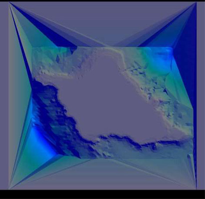
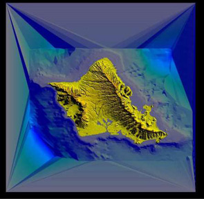
| Project 1 Terrain Result Graphic |
|
 |
| |
| Phase 2 . Combining Below & Above Sea Level Elevation Data. |
| |
| The purpose of Phase 1 is to create elevation data for under the ocean. This data can be used in
a new Terra Vista project to build the sea floor. If you are only building an underwater terrain
and are not concerned about any coastline or above sea level terrain, you can proceed to Phase
3 of this tutorial and build your underwater database using the terrain exported from Phase 1. |
| |
| However, the Phase 1 terrain data does not contain elevation information above water. If you
want build a database with both above and below water terrain data you will need to combine
the output from Phase 1 with normal elevation data prior to moving on to phase 3. Terra Vista
will not automatically combine it for you. We recommend using Global Mapper for this process. |
| |
| Global Mapper Workflow |
|
1. Open Global Mapper, and load your below sea level elevation data derived from the Phase 1
Bathymetry Terra Vista project. This could be either DTED 2 or 3 files. They will be in the
project’s convert directory.
2. Load your elevation data for above sea level terrain such as DTED, DEM, STRM. For this
example you can load the file \source\elevation\srtm.tif. You will be able to see everything in
Global Mapper. Verify you have valid above water elevations and below water elevations.
Ensure the layers are displayed correctly using the Overlay control center. Check for coast line
correlation between the files.
3. At this point in time, it may be necessary to cut and clip the above sea level elevation file to
get rid of sea level zero Z terrain texels and match the elevation to the coastline. This is where
a correlated areal vector file will come in handy. ECRAREA.AFT file will contain island, land, and
ocean surface areal polygons correlated to the coast line vector. This file can be used since it
correlates to the source coast line vectors. It is located in folder
source\bathymetry\DNC13\A1356285\ECR. You can use global mapper to delete the non land
area features from this file or Terra Vista Vector editor and shape file exporter. When the land
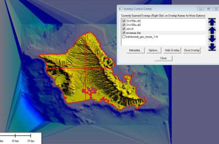
and island layer is complete, import this file into Global Mapper and overlay it as the top layer. |
| |
| Global Mapper Display layer setup Graphic |
|
 |
| |
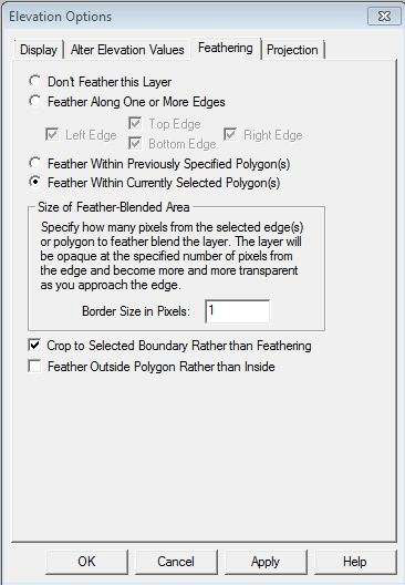
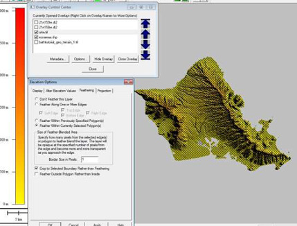
4. The above sea level elevation will need to be clipped at the coastline using this areal land
feature file. At this time, disable the below sea level elevation files. Then, use the editor tool to
select all the areals representing land from the land layer file. Next, select the srtm.tif file and
enter the Options menu from the Overlay control center. Go to the Feather tab and set up the
feather parameters as pictured in the graphics below and apply the feather. This will clip the
above sea level terrain texels to the area polygon boundaries. |
| |
 |
| |
 |
| |
| 5. At this time, verify the results. Restart the process if you did not get the desired result or try
different feather options.6. Turn back on the bathymetry terrain elevation files. Disable the areals. Export the data to
GeoTIFF format selecting Elevation (16 bit integer samples), and selecting Interpolate to Fill
Small Gaps in Data. If you are processing large amounts of data you should grid the output into
geocells by setting Grid Width and Height to 1 arc degrees on the Gridding tab. Remember to
set the bounds of your export area. |
| |
| 6. Turn back on the bathymetry terrain elevation files. Disable the areals. Export the data to
GeoTIFF format selecting Elevation (16 bit integer samples), and selecting Interpolate to Fill
Small Gaps in Data. If you are processing large amounts of data you should grid the output into
geocells by setting Grid Width and Height to 1 arc degrees on the Gridding tab. Remember to
set the bounds of your export area. |
| |
| Note: You may want to output a higher resolution terrain than DTED 2 to get a smoother
coastline in the output OpenFlight. This will ensure you do not end up with land texels in the
water area and water elevation texels on the land area due to the coarseness of DTED 2. |
| |
| 7. You should now have a single elevation file containing above sea level and below sea level
elevation matching your coastline vectors. You are ready to use this file to produce your
bathymetry database. |
| |
 |
| |
| |
| Phase 3 / Project 2. Building the Final Bathymetry Database. |
| |
| The phase 3 project is designed to build a database using the raster terrain files generated from
the Phase 1 project or the Phase 2 Global Mapper exported raster terrain file. |
| |
1. Create a new Terra Vista project for building the final database.
2. When the Interviewer opens, input your new elevation data from Phase 1 or Phase 2
depending on your requirements. Also input any imagery and vector data you want in your
database. Set LODs, Polygons per LOD, extents, and others as desired. Using Defaults is OK
here.
3. Open the Thumbnail view and go to the Gaming Area tab.
4. Set the Block Size to 0.1 degrees in X and Y.
5. Set the Extents to 21N to 22N and 158.5W to 157.5W.
You should have 10 x 10 blocks.
6. At this point, you have two options. You can build a flat ocean surface polygon using an
ocean texture type database or you can just build terrain and use the Vega Prime Marine
module to have 3D marine ocean states surrounding the terrain and islands. |
| |
| Vega Prime 3D Marine State Database Process |
|
| 7. Import the linear coast line vector file from the first project. This vector will be used in this
project as it was in project 1 to clamp the coast line in the output geometry to zero z. Cool
Idea: You could also use these features to build Terra Vista complex geometry features such as
sea walls or quays. Be sure to set up linear feature model Shoreline/Coastline (contours) to
make the coastline be zero Z. |
| |
| 8. Build all. Then load the result in either Creator or Vega Prime using the Marine feature to see
the 3D ocean surrounding your islands. See Vega Prime Marine help for this setup or use the
supplied Vega Prime 5.0.1 acf file bath_marine.acf under source/acf directory. You will need to
set up the search paths and object flight file in your acf. |
| |
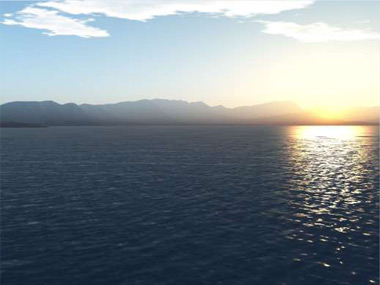
| Vega Prime Result Graphic |
|
 |
|
| Flat Ocean Surface Polygon with Ocean Texture Database Process |
| |
7. In the source tab, Select File/Import and import
\source\bathymetry\DNC13\A1356285\ECR\ECRAREA.AFT. This file contains areals for the
ocean(code=BA040) which we can use to texture the sea floor and create the ocean polygons at
sea level. The file also contains areals for the land masses (code=BA030) which we will ignore. |
| |
| Note that the ocean areals do not extend to the edges of the database. In order to build a
proper and complete database these vectors should be extended beyond the edges of the
database to have complete ocean coverage. For now, this is not needed but it is something to
consider for real projects. |
| |
| 8. Look on disk in your Terra Vista project directory there will be a 'convert' directory. Within
this convert directory is a file named ECRAREA.vec which is the ocean information we just
loaded. Copy and paste this file and give it the name ECRAREA2.vec. We need two copies ; one
we will use to create the textured sea floor and the other will create the textured sea surface. |
| |
| 9. In Terra Vista import this new ECRAREA2.vec file and use the Vector Editor to change all of
the areals with code=BA040 to code=seafloor. Remember to save the vector file. |
| |
| 10. In Culture Parameters;Default;Feature Models, disable Dart, Point, and Linear because we
do not need them. In your future projects you may need them, and you can use them. Under
Areal, create a new folder called NotUsed and put everything in there except Footprint, Buffer,
Presagis Control, and Catch All. Then disable the NotUsed folder. If you place it below the Catch
All feature model it will not be used. |
| |
| 11. Copy the Cropland feature model from NotUsed under Areal and make sure it is above
Catch All. |
| |
| 12. Rename the copy of Cropland to Ocean-Surface and set the Selector to "code = BA040". |
| |
| 13. Make a copy of Ocean-Surface. Name it Ocean-Floor and set the Selector to "code =
seafloor". |
| |
| 14. For Ocean-Floor, make sure that SetElevations is enabled, Action is setDem, and Height
Source is Use DEM. |
| |
| 15. For Ocean-Floor, make sure that Set Culture Layout is enabled, Output Layout is Stitched,
and Lower LOD Representation is Stitched. This will give you a ocean bottom textured with
texture you select. |
| |
| 16. For Ocean-Floor, make sure Generate Areal is enabled and set the Poly Attr to a good seafloor
texture such as Property Library;Default;Polygons;Ground Surfaces;sand01.17. For Ocean-Surface, make sure that Set Elevations is disabled. This will set the Ocean surface
to zero Z because features with no Set Elevations will set the elevation to the Z on the vertex,
which is zero on a 2D vector file. |
| |
| 18. For Ocean-Surface, make sure that Set Culture Layout is enabled, Output Layout is
Floating,and Lower LOD Representation is Floating. This will give you a ocean surface floating a
Zero Z in the output geometry. |
| |
| 19. For Ocean-Surface, make sure Generate Areal is enabled and set the Poly Attr to a good seasurface
texture such as Property Library;Default;Polygons;Hydrography;sea01. |
| |
| 20. Build All.21. Examine the results in Creator by opening individual files or mas ter.flt. You can also look at
the data with the Terra Vista 3D viewer. You can also load this database into Vega Prime. |
| |
| The bathymetry database tutorial is now complete. You should be able to use these concepts
to use your own nautical information source files to build a bathymetry marine database. You
could also use these projects as your default Terra Vista projects for bathymetry database
creation. |
| |
| Click here for downloading the source code |
| |