|
| Tips & Tricks |
| |
| 1. DLName Settings in Catia V5 |
| |
| When project data is being maintained in file base environment (folders) instead of PDM, it is important to maintain all the data being stored in right location by all the users working on the project, to avoid the duplication of the data in multiple locations. CATIA provides tool like DLNAME to avoid such situation. |
| |
This feature works the same as the DL Name in CATIA V4
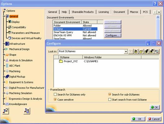
In CATIA V5, DLName Setting is under Tools>Options>General>Document. |
| |
 |
| |
- First activate DLName, select DLName and Change to Allowed.
- Configure DLName.
- Select Defines a DLName, to add a new DLName.
- Click on the DLname1 to define your DLName, and Window Folder to define your folder path.
- Click Ok to accept the new DLName.
- Click on Current to set the DLName option as the default.
- Click on the Folder option and select Not Allowed
- Click Ok to save the settings.
- Next time when File>open or File>Save option is used we will get on this window, since user will not get to see the other folder on the drive, we can avoid the data duplication.
|
| |
| 2. METHODOLOGY FOR DRAFTING LARGE ASSEMBLIES |
| |
| There are many different techniques that can be employed to improve the performance when working with the drafting of large assemblies. Simply put, use smart drafting techniques to generate in drafting only what are needed for the views. This will keep the data size down, which yields the best performance. If the smart drafting techniques aren’t sufficient, the assemblies should be simplified using the Convert Product to CATPart function. The following two sections show some of the smart drafting techniques and discusses simplified assemblies. |
| |
| Examples of Smart Drafting Techniques for Large Assemblies |
| |
- Limit the number of scenes to the minimum number necessary to convey the Visualization of the assembly. Each scene created substantially increases the size of the CATProduct.
- Create Raster-generated views as images. This allows the user to quickly generate overall views for large assemblies that can be opened in visualization mode. Although there are restrictions on generating raster views, when used, they reduce data size and improve addressable memory usage.
- Manually manage which elements are shown in the assembly, before generating those views. Anything that shouldn’t be seen in the view should not be visible in the assembly.
- Create views by multi-selecting only the nodes in the tree of the elements intended to be seen in the drawing, not the entire assembly.
|
| |
| Simplified Assemblies |
| |
| A simplified assembly is created when the contents of an assembly are merged into one or more CATParts and then reassembled into a new CATProduct. The selected components of the original CATProduct(s) are converted into individual bodies within the CATParts. Assemblies over 200MB should be considered for the creation of simplified assemblies. Assemblies should be simplified using the Convert Product to CATPart function if the smart drafting techniques are not sufficient. Simplifying assemblies is best done after the design is nearly completed and ready for detailing. This technique is not intended to be used during the stages of the design when changes often occur because manual synchronization of the original data is required if there is a change. |
| |
| |