Development process of the automobile part modules usually requires various kinds of numerical simulations to reduce the number of prototypes. In the past engineers had been forced to use several tools for different types of Finite Element (FE) based stress analysis, even though the simulation processes are well defined, since no FE based stress analysis software had not provided various capabilities required for the development process. Due to severe competition in the current market situation, automobile companies and their part suppliers should reduce the time to market and costs for the development to keep them as competitive as they can. Thus, the lesser time engineers are allowed in designs, the more need for effective tools that can handle almost all of their numerical procedures are expected.
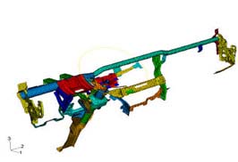
A cockpit module is one of the extremely complex vehicle components. The cockpit module of automobiles usually consists of an instrument panel (IP), a steering column system, a HVAC system, a glove box, a cowl cross structure, various trays, an audio and navigation system, and decorative facials. Development of a cockpit module requires a lot of simulation work to verify its performance prior to prototyping. To satisfy its design goals and to meet various regulations, numerical analysis of passenger air bag (PAB) deployment, head impact and knee impact protection, thermal deformation, NVH, and CFD has been frequently adopted as effective means of design verification.
Using Abaqus unified finite analysis modeling approach can handle:
- Head impact
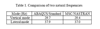
- Natural frequency extraction
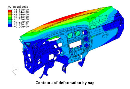
- Sag
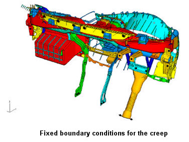
- Creep
Head Impact Analysis
According to FMVSS 201, the standard’s test procedure requires that a headform with 165mm in diameter and 6.8 Kg in mass impacts the interior at an initial velocity of 19.2 Km/h with an airbag and 24.1 Km/h without it, respectively. The standard regulates that the acceleration at the center of the headform should not exceed 80g during any 3 milliseconds interval.
ABAQUS/Explicit is used to simulate the behavior of the cockpit module on impact load conditions. Shell elements used in this analysis are S3RS and S4RS that are well suited to shell problems with small membrane strains and arbitrary large rotations. Many impacts dynamic analyses may fall within this class, including those of shell structures undergoing large-scale buckling behavior but relatively small amounts of membrane stretching and compression.